


Heat Pipes
Introduction of Micro Heat Pipe
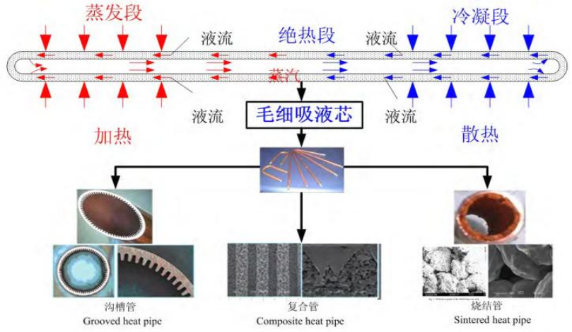
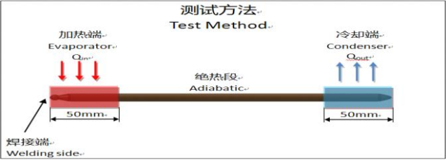
As shown in the diagram of heat transfer principle of heat pipe, one end of the heat pipe is evaporation zone (heat in) and the other end is condensation zone (heat out). When the evaporation zone is heated, liquid working-fluid in capillary wick is vaporized, the vapor flows to the condensation zone driven by the pressure difference between the hot evaporation zone and the cold condensation zone and then condensates in the condensation zone. The working-fluid, which is transformed into liquid, flows from the condensation zone to the evaporation zone along the capillary structure driven by the capillary pressure. In a cycle like this, heat is transferred from one end to the other of the heat pipes.
Different applied environment and working conditions requires different micro heat pipe with a different structure and heat transfer performance. The heat transfer performance of micro heat pipes relies heavily on the capillary wick structure in the inner surface, so design and manufacturing technology of the wick structure is the key and critical factor in the production process of the micro heat pipe at all time.
According to different wick structure, micro heat pipe includes three types: grooved heat pipe, sintered heat pipe and composite heat pipe.
Micro heat pipe structure and working principle
Heat Pipe Products
• Heat Pipe Display
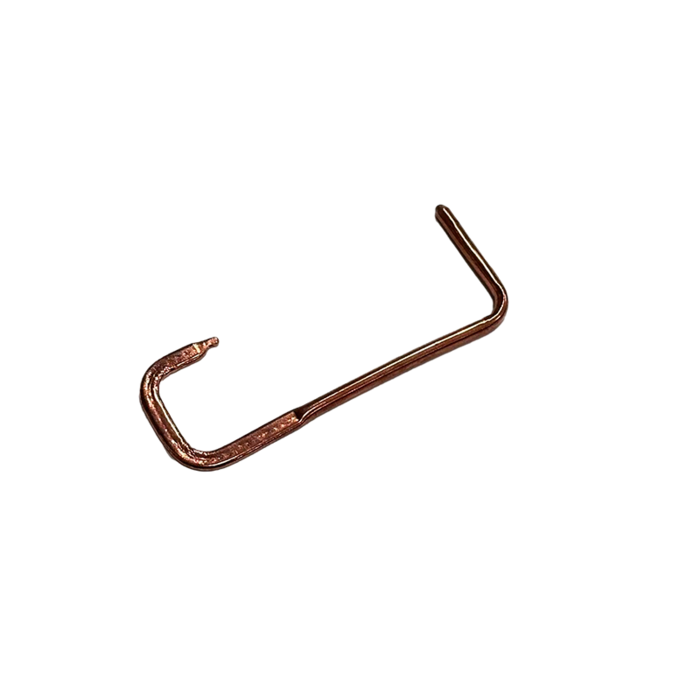
• Straight Heat Pipe
• Flat Heat Pipe
• Special-Shaped Heat Pipe
Heat Pipe Type
Diameter (mm): 1,2,3,4, 5,6,8,10,9.5,12,12.7,16,22
Length(mm): 60~1000
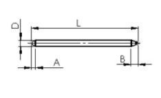
| Diameter(D) | Standard Length(L) | Ineffective Length(A) | Ineffective Length( B) |
| 1±0.05mm | 60~300±1mm | 1~3.0mm | 1~6.0mm、<8mm |
| 2±0.05mm | 60~300±1mm | 1~3.0mm | 1~6.0mm、<8mm |
| 3±0.05mm | 60~300±1mm | 2~5.0mm | 4~7.0mm、< 10mm |
| 4±0.05mm | 60~300±1mm | 2~5.0mm | 4~7.0mm、< 10mm |
| 5±0.05mm | 60~300±1mm | 2~5.0mm | 4~7.0mm、< 10mm |
| 6±0.05mm | 60~2000±1mm | 2~5.0mm | <10mm |
| 8±0.05mm | 60~2000±1mm | 3~5.0mm | <10mm |
| 9.5±0.05mm | 60~600±1mm | <5mm | <14mm |
| 10±0.05mm | 60~600±1mm | <5mm | <14mm |
| 12±0.05mm | 60~600±1mm | <5mm | <15mm |
| 12.7±0.05mm | 60~600±1mm | <8mm | <15mm |
| 16±0.05mm | 60~600±1mm | <8mm | <15mm |
| 22±0.05mm | 60~600±1mm | <8mm | <15mm |
Bending Suggestion
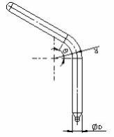
| R and Angle | ||||
| Type | Min. R | Suggestion | Min.Bending Angle | Suggestion |
| Φ3 | 6 | 12 | 180 °> | 180 °> |
| Φ4 | 7 | 16 | ||
| Φ5 | 9 | 20 | ||
| Φ6 | 9 | 24 | ||
| Φ8 | 16 | 32 | ||
| Φ10 | 18 | 40 | ||
| Φ12 | 20 | 48 | ||
Width Table of Flatted Heat Pipe
| Diameter | Thickness | Tolerance | Wide | Tolerance | Diameter | Thickness | Tolerance | Wide | Tolerance |
| Φ3 | 2.5 | ±0.05 | 3.32 | ±0.15 | Φ6 |
3.5 | ±0.05 | 7.6 | ±0.15 |
| 2 | 3.65 | 3 | 7.84 | ||||||
| Φ4 | 3.6 | ±0.05 | 4.3 | ±0.15 | 2.9 | 7.91 | |||
| 3 | 4.68 | 2.5 | 8.13 | ||||||
| 2.5 | 4.95 | 2 | 8.54 | ||||||
| 2.3 | 5.08 | 1.5 | 8.86 | ||||||
| 2.2 | 5.14 | 1.2 | 8.98 | ||||||
| 2 | 5.24 | 1 | 9.05 | ||||||
| Φ5 | 4 | ±0.05 | 5.75 | ±0.15 | Φ8 | 5 | ±0.05 | 9.96 | |
| 3.5 | 6.03 | 4.7 | 10.16 | ||||||
| 3 | 6.29 | 4.5 | 10.2 | ||||||
| 2.5 | 6.54 | 4.2 | 10.45 | ||||||
| 2.3 | 6.66 | 4 | 10.5 | ||||||
| 2 | 6.8 | 3.8 | 10.58 | ||||||
| Φ6 | 5.3 | ±0.05 | 6.62 | ±0.15 | 3.5 | 10.71 | |||
| 5 | 6.82 | 3.2 | 10.9 | ||||||
| 4.8 | 6.92 | 3 | 10.97 | ||||||
| 4.5 | 7.08 | Φ10 和Φ9.5 | 定制 | ||||||
| 4.3 | 7.2 | Φ12 | |||||||
| 4.2 | 7.24 | Φ12.7 | |||||||
| 4 | 7.34 | Φ16 | |||||||
| 3.8 | 7.46 | Φ22 | |||||||
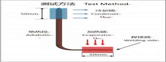
Q-max Test Method For Heat Pipe
Test Method :
1. THeat Source=70±5℃
2. TCondencer =50℃
3. DB=50mm
4. DA=50mm
5. TambieNIT =25±3℃
6. Find the Q-max while T1-T2≤5℃
 |
 |
| Q-MAX |
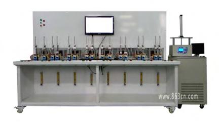
Thermal Performance Test
Data Obtained
| Q-max Table (Watt) | ||||||
| Flatten Thickness | Ф5mm | Ф6mm | Ф8mm | |||
| Min. Power | Avg. Power | Min. Power | Avg. Power | Min. Power | Avg. Power | |
| T=2.5mm | 35 | 36 | 38 | 40 | 40 | 45 |
| T=3.0mm | 35 | 38 | 40 | 43 | 52 | 55 |
| T=3.5mm | 40 | 41 | 42 | 45 | 57 | 60 |
| Round Pipe | 45 | 48 | 48 | 50 | 60 | 67 |
(Note: The data comes from the experimental results in 2008)
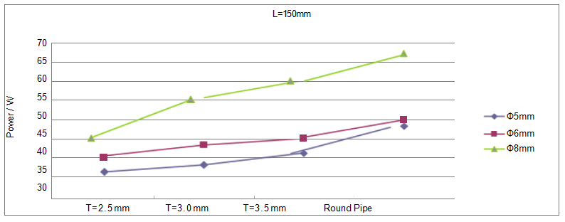
Thermal Performance Test
type:straight pipe Heat Pipe by L=200mm

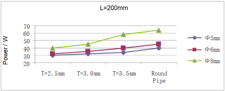
Data Obtained
| Q-max Table (Watt) | ||||||
| Flatten Thickness | Ф5mm | Ф6mm | Ф8mm | |||
| Min. Power | Avg. Power | Min. Power | Avg. Power | Min. Power | Avg. Power | |
| T=2.5mm | 28 | 30 | 30 | 32 | 35 | 40 |
| T=3.0mm | 30 | 32 | 33 | 35 | 40 | 45 |
| T=3.5mm | 33 | 34 | 35 | 40 | 55 | 58 |
| Round Pipe | 35 | 40 | 40 | 45 | 58 | 64 |
(Note: The data comes from the experimental results in 2008)
Thermal Performance Test
type: L pipe Evaporator=50mm
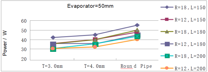
(Note: The data comes from the experimental results in 2008)
Data Obtained
| Q-max Table (Watt) | ||||||||||||
| Specification | Ф6×150 | Ф6×180 | Ф6×200 | |||||||||
| Bending radius | R=18mm | R=12mm | R=18mm | R=12mm | R=18mm | R=12mm | ||||||
| Flatten Thickness | Min. | Avg. | Min. | Avg. | Min. | Avg. | Min. | Avg. | Min. | Avg. | Min. | Avg. |
| T=3.0mm | 40 | 42 | 33 | 35 | 32 | 35 | 32 | 35 | 28 | 30 | 28 | 30 |
| T=4.0mm | 43 | 45 | 38 | 40 | 35 | 40 | 33 | 35 | 32 | 35 | 30 | 32 |
| Round Pipe | 52 | 55 | 45 | 48 | 48 | 50 | 43 | 45 | 40 | 43 | 38 | 40 |
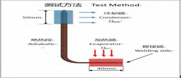
Thermal Performance Test
type:L pipe Evaporator=40mm
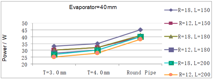
Data Obtained
| Q-max Table (Watt) | ||||||||||||
| Specification | Ф6×150 | Ф6×180 | Ф6×200 | |||||||||
| Bending radius | R=18mm | R=12mm | R=18mm | R=12mm | R=18mm | R=12mm | ||||||
| Flatten Thickness | Min. | Avg. | Min. | Avg. | Min. | Avg. | Min. | Avg. | Min. | Avg. | Min. | Avg. |
| T=3.0mm | 32 | 33 | 29 | 30 | 29 | 30 | 27 | 28 | 25 | 27 | 23 | 25 |
| T=4.0mm | 33 | 35 | 30 | 32 | 30 | 32 | 29 | 30 | 28 | 30 | 26 | 28 |
| Round Pipe | 43 | 45 | 38 | 40 | 40 | 41 | 38 | 40 | 38 | 40 | 36 | 38 |
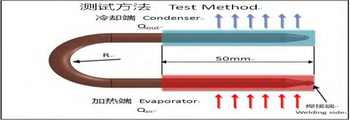
Thermal Performance Test
type:U pipe Evaporator=50mm

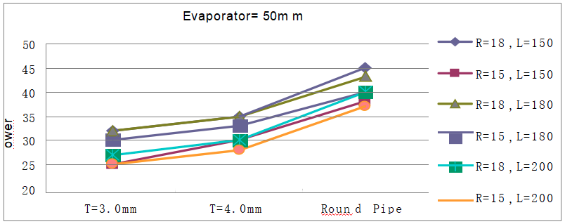
Data Obtained
| Specification | Ф6×150 | Ф6×180 | Ф6×200 | |||||||||
| Bending radius | R=18mm | R=15mm | R=18mm | R=15mm | R=18mm | R=15mm | ||||||
| Flatten Thickness | Min. | Avg. | Min. | Avg. | Min. | Avg. | Min. | Avg. | Min. | Avg. | Min. | Avg. |
| T=3.0mm | 30 | 32 | 23 | 25 | 30 | 32 | 28 | 30 | 26 | 27 | 23 | 25 |
| T=4.0mm | 33 | 35 | 29 | 30 | 33 | 35 | 30 | 33 | 28 | 30 | 27 | 28 |
| Round Pipe | 42 | 45 | 37 | 38 | 40 | 43 | 38 | 40 | 38 | 40 | 35 | 37 |
Thermal Performance Test
type:U pipe Evaporator=40mm
Data Obtained
| Specification | Ф6×150 | Ф6×180 | Ф6×200 | |||||||||
| Bending radius | R=18mm | R=15mm | R=18mm | R=15mm | R=18mm | R=15mm | ||||||
| Flatten Thickness | Min. | Avg. | Min. | Avg. | Min. | Avg. | Min. | Avg. | Min. | Avg. | Min. | Avg. |
| T=3.0mm | 27 | 28 | 25 | 26 | 23 | 25 | 20 | 23 | 21 | 23 | 20 | 22 |
| T=4.0mm | 30 | 32 | 28 | 30 | 29 | 30 | 26 | 28 | 27 | 28 | 24 | 26 |
| Round Pipe | 36 | 38 | 35 | 36 | 34 | 35 | 31 | 33 | 30 | 32 | 28 | 30 |
Relationship between power and length(Sintered Heat Pipe)
Relationship between power and length(Grooved Heat Pipe)
Relationship between power and thickness of heat pipe
Manufacturing Process of Heat Pipe
Heat Pipe Reliability Test
1.Testing diameter and △T
2.Heating at 150℃ for one hour
3.Testing diameter and △T again
4.Heating at 150℃ for twelve hour again
5.Testing diameter and △T again
Objective:
The purpose of this examination is to test the heat pipe stability which depends on how long the heat would change the shape and performance of the heat pipe in high temperature.
Isothermal test of heat pipe
1. Theat source =70℃±5℃
2. Heating Time T≤15s
3. Check the temperature in upper edge of heat pipe T1
4. Check △T ,△T ≤4℃ , (△T =T-T1)。
Isothermal test of heat pipe
1.Theat source =70℃±5℃
2. Heating Time T≤15s
3. Check the temperature in upper edge of heat pipe T1
4. Check △T ,△T ≤4℃ , (△T =T-T1)。
Objective:
The purpose of this examination is to see the stability of heat pipe, ensuring there are no defective goods after testing.
Thermal Cycle Test of Heat Pipe
Objective:
From testing ,the useful life and aging rate is revealed.
Our Heat Pipes
Operation Temperature 5~222℃
Burst Temperature(℃) 340℃(备注:增大壁厚可以提高破坏温度)
Useful Life@80℃operation temperature >7年 Years
Heat Pipe Reliability Experiments
1. Useful life Test
2. Leakage Test
3. Performance Test
4.Thermal Cycle Test
5. Salt Spray Test